


 수량을 선택해주세요.


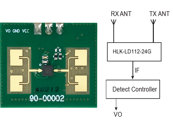
24GHz 밀리미터 마이크로웨이브 레이더 센서 -LD112-24G
(24GHz Millimeter Microwave Radar Sensor -LD112-24G)


개요
- 본 제품은 24GHz 밀리미터 마이크로웨이브 레이더 센서 -LD112-24G입니다.
- 좁은 범위내에서 움직이는 물체를 탐지하고자 할때 사용이 가능한 제품으로 HIGH/LOW 출력 정보를 내보냅니다.
- 먼지와 같은 다양한 종류의 생활 이물질은 자동으로 필터링합니다.
- 5V로 동작합니다.
특징
-
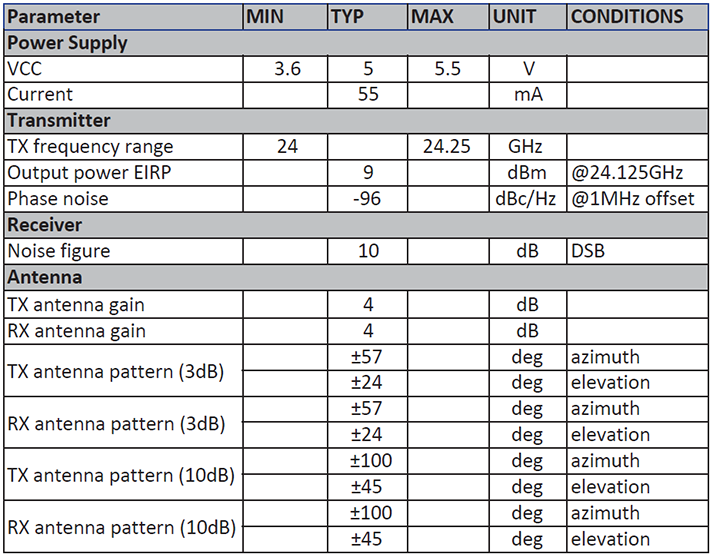
TX frequency range: 24-24.25GHz
TX EIRP: 9dBm
Phase noise: -96DBC /Hz @1mhz offset
RX noise factor: 10 dB DSB
5V Power current: 55mA
Small size: 22.95mm x 20mm
-
Electrical characteristics (at 25°C)
문서
-
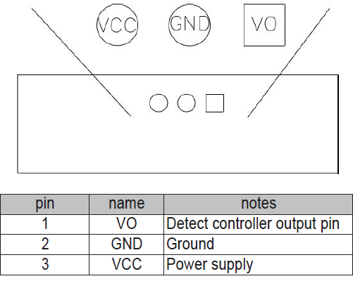
Connection instructions
The pin is 2.54mm 1×3 pin connector connection.
-
Module dimensions

-
Parameter debugging method
* VO: Detection level output. When a person or an object is detected to move, it outputs a high level for about 1 second. Low level when there is no object moving.
* GND: Ground.
* VCC: Power supply. The version with LDO is powered by a 5V power supply.1.Sensitivity debugging method A
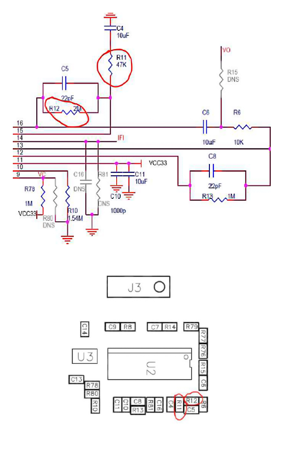
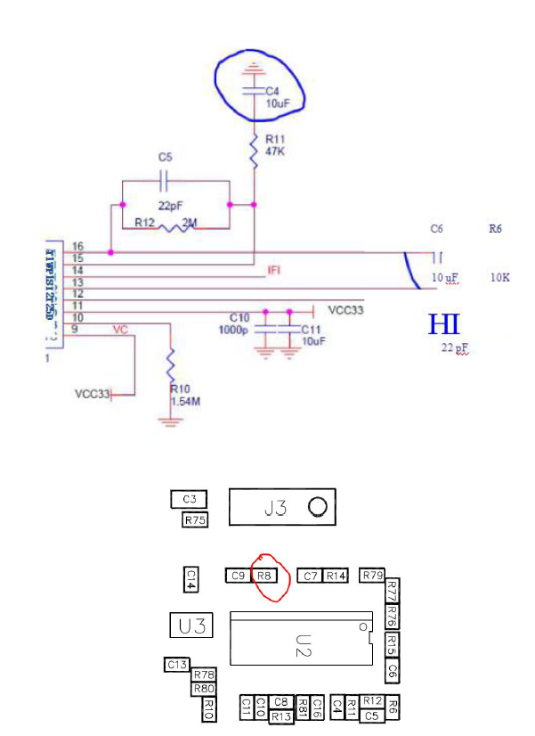
A1. Current sensitivity magnification=(R12/R11)*(R13/R6)=(1M/20K)*(1M/10K)=5000 times. Considering that some shell materials have greater attenuation of electromagnetic waves, the default sensitivity is 5000 times, which is a relatively sensitive value. The sensitivity can be modified according to actual application scenarios.
A2. If you need to reduce the sensitivity, it is recommended to directly change the resistance of R11 and increase the resistance of R11. For example, if you need to modify it to 2000 times, then just change R11 to 50k.
1-2. Sensitivity debugging method B
Decreasing the capacitance of C4 and C6 can change the link bandpass characteristics and increase the high-pass cutoff frequency. In this way, the module will be insensitive to some minor actions, and the module will be more stable and difficult to trigger. At the same time, the initial startup time of the module can be greatly reduced. It is recommended to change to 2.2uF or 1uF. Specific effects can be debugged according to actual conditions. The side effect is that the sensing distance will be reduced by about 20%.
2. Block time debugging method
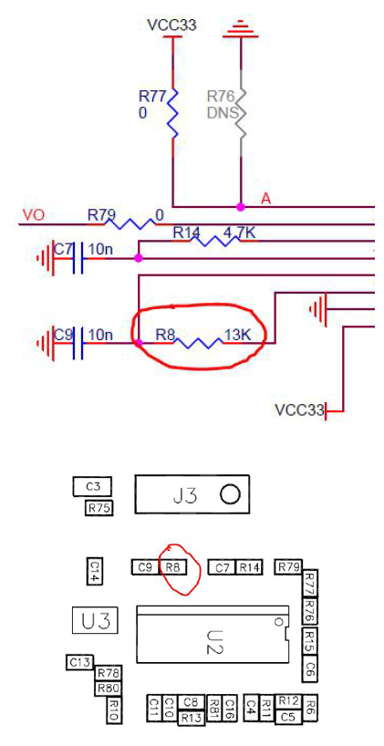
A1. Blocking time refers to the time after the current detection is completed and the output level returns to 0 level until the next detection takes effect. This time can be adjusted by changing the resistance of R8.
A2. The current blocking time is about 0.8 seconds, corresponding to R8=39k. It is not recommended to reduce it. If the blocking time is too small, the module will be easily triggered by interference. An excessively large R8 will cause the module to underreport.
The approximate relationship between block time and R8:

3. Debugging method of high-level output maintenance time after trigger

A1. The high level maintenance time after triggering is the maintenance time for the module to output 3.3V high level after detecting a moving object.
A2. The current high-level output sustain time is about 1 second, corresponding to 14=4.7k. The value of R14 corresponding to the output holding time is shown in the table below.
The current module is powered by 5V, and there is an LDO on the module to change 5V to 3.3V, so VD=3.3V shall prevail.


