수량을 선택해주세요.


24GHz 밀리미터 마이크로웨이브 레이더 센서 -LD303-24G
(24GHz Millimeter Microwave Radar Sensor -LD303-24G)


개요
- 본 제품은 24GHz 밀리미터 마이크로웨이브 레이더 센서 -LD303-24G입니다.
- 좁은 범위내에서 움직이는 물체를 탐지하고자 할때 사용이 가능한 제품입니다.
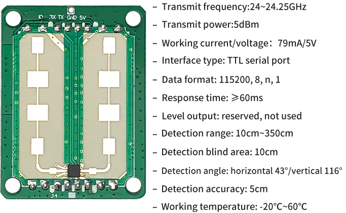
- 온도, 습도, 공기 흐름, 먼지, 소음, 밝기 등에 영향을 받지 않는 제품으로 5V로 동작합니다.
- 5V로 동작하여 시리얼 인터페이스를 가지고 있습니다.
- 검출가능 거리는 10-350cm입니다.
특징
-
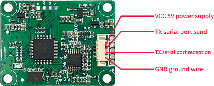
- *The interface is a 4-pin lock terminal with a pitch of 1.25mm
문서
-
Communication configuration
TTL serial port, default baud rate 115200, data bit 8, stop bit 1, no check bit. Fixed query command (HEX): 55 5A 02 D3 84. The module defaults to the query mode, sending a fixed hexadecimal query command, and the module reports distance and other data after receiving it successfully.
Communication format
A. Uplink data (send by module)
Word threshold Frame header length address distance Reserved status Signal strength Fretting Radar off check Number of bytes 2 1 1 2 1 1 2 1 1 1 content 55A5 0A D3 XX XX X XX X X XX *the data shows
Length: the number of bytes except the frame header and check byte, 0x0A, fixed byte
-Address: 0xD3, fixed byte;
-Distance: The unit is cm, which occupies 2 bytes, with the high order first;
-Reserved: 1 byte, value 0x00, fixed byte;
-Status: target presence or absence; 1 byte, 0: no one 1: no one;
-Signal strength: unit: k, occupies 2 bytes, high order first;
-Inching: Value 0 or 1; 0-no inching, 1-with inching;
-Radar off: Whether the radar is off, the value is 0 or 1, 0-not off/1-off;
-Check: Sum check, all bytes except check word threshold are sum, and the lower 8 bits are taken, occupying 1 byte.eg:
55 A5 0A D3 00 58 00 01 01 4C 01 01 7F
Available: There are people in the detection area, the distance is 88cm, and the signal strength is 332k.B. Downlink data (module receiving)
Word threshold Frame header address Command number Command parameters check End of frame Byte length 2 1 1 2 1 2 content BAAB 00 ES XX 00 55BB *the data shows
Frame header: fixed 2 bytes, 0xBAAB
-Address: 0x00, fixed byte;
-Command number: the command number for setting the maximum detection distance, 0xE5, fixed byte;
-Command parameters: set the maximum detection distance, occupying 2 bytes, with the high order first;
-Check: No check, 0x00, fixed byte;
-End of frame: fixed 2 bytes, 0x55BB;
-Return after successful setting: 0D 0A 77 72 69 74 65 20 6F 6B 0D 0A
That is, the ASII code "Enter + write ok + enter"Module dimensions

Precautions
* The module detects relative moving objects in the area, and outputs information such as the distance of the object, and completely stationary targets are not detected.
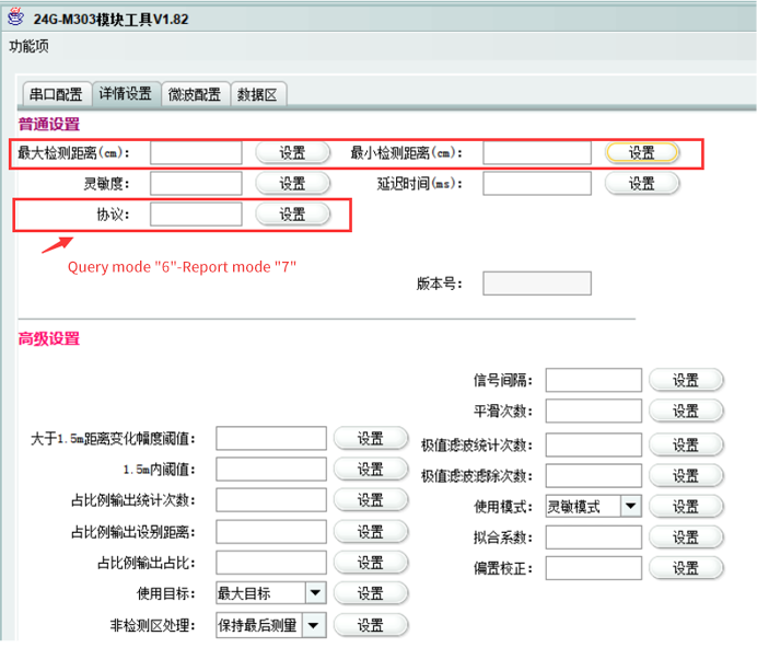
* The default query mode (protocol 6), if you need continuous automatic reporting, change the protocol to 7. (Use the host computer to modify or send the instruction directly BAAB00F600070055BB)
* If the module design shell, the best distance between the radar antenna surface and the shell surface is 6mm, and the thickness of the shell is about 2~3mm. The shell material can not use metal or metal-plated paint. It is recommended to use PC or plastic or steel Wait.Relationship between angle and farthest distance
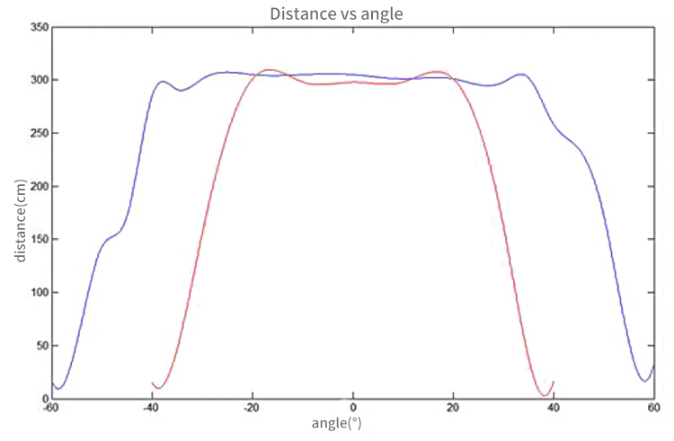
*test introduction
-Test target: human body;
-Installation: horizontal installation and vertical installation respectively;
-Red broken line: The module is installed horizontally, with the module as the center of the circle, the vertical line of the antenna surface is 0°, and each angle and the angle correspond to the longest distance relationship that can be detected;
-Blue fold line: The module is installed vertically, with the module as the center of the circle, the vertical line of the antenna surface is 0°, and each angle and angle correspond to the fold line of the farthest distance that can be detected.Module host computer demo
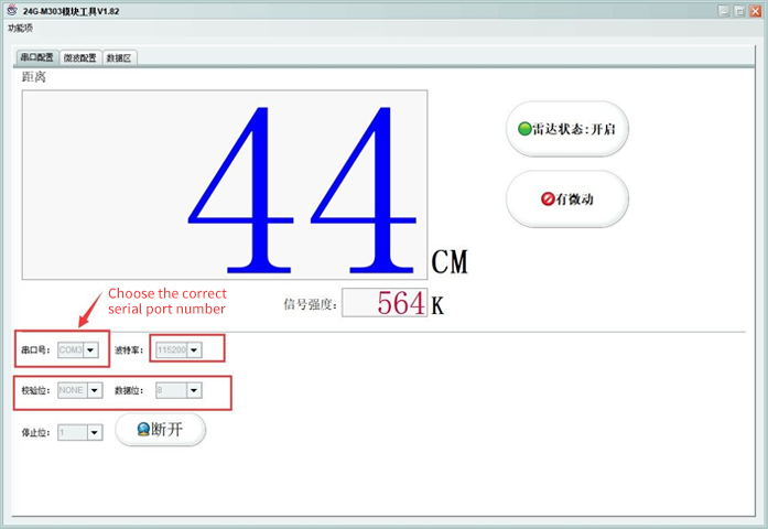
1. Connect the serial port of the module according to the terminal guide in the figure above (please ignore the PCB printing when using the terminal, because the terminal is drawn from the drawing board), and connect the other end to the computer USB port (I use the CP2104 serial port to USB small board here) ), select the currently used serial port number, the baud rate is 115200, and the rest are just as default.
2. Regarding the modification of the maximum detection distance and sensitivity related settings of the module, please refer to the range value of the instruction table for details. It is not recommended to modify other than the maximum and minimum detection distance. (How to open the configuration item, the upper left corner of the host computer "function item"-"developer configuration"-key, please contact customer service. * Emphasis-if the parameters are modified, the batch will be released later Please be sure to contact the salesperson to burn the firmware according to the modified parameters of the test)