


 수량을 선택해주세요.


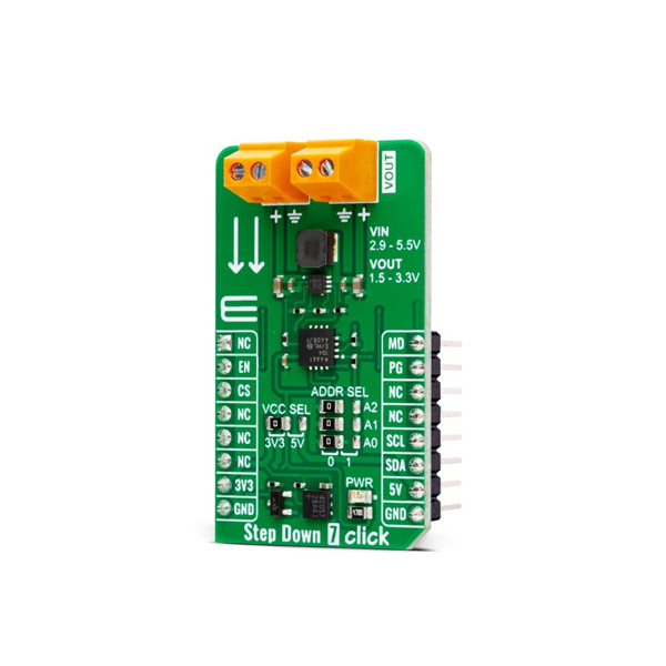
DC-DC 스텝다운 컨버터 모듈 -MAX17624
(STEP DOWN 7 CLICK)
개요
- 본 제품은 DC-DC 스텝다운 컨버터 모듈 -MAX17624 입니다.
- MAX17624 칩을 기반으로 디자인된 제품으로 2.9V-5.5V의 전압을 입력 받아 1.5V-3.3V(1A) 전압을 출력할 수 있는 제품입니다.
- MAX17624 는 PWM 및 PFM 동작 모드 설정이 가능합니다.
- 3.3V/5V 시스템과 사용이 가능합니다.
특징
-
HOW DOES IT WORK?
Step Down 7 is based on the MAX17624, a synchronous step-down converter with integrated MOSFETs from Analog Devices. The converter uses soft start ramp technology, allowing a smooth output voltage increase. The output voltage is monitored through a resistor divider as feedback. On this Click board™, the resistor divider consists of a resistor, and the MCP4661T, an 8-bit dual digital POT with volatile memory from Microchip. This 50K digital potentiometer has a resistor ladder with ends connected to the analog switches and terminals A and B. The 256 resistors give 257 wiper positions. The potentiometer features high-speed read/write to the wiper and increment/decrement of wiper serial protocols.
.jpg)
The MAX17624 has two selectable modes of operation, the PWM and the PFM modes. The PWM mode is used in fixed-frequency operations with a fixed 4MHz switching frequency. This mode allows the device's output current to go negative and is useful in frequency-sensitive applications as it provides fixed switching frequency operations at all loads. The PWM mode gives lower efficiency at light loads compared to a PFM mode of operation. The PFM mode disables the negative output current from the device, and skips pulses at light loads for better efficiency. Another feature of the step-down converter is Power Good, which indicates the output voltage status.
Step Down 7 Click uses I/O pins to communicate with the host MCU. To change to the desired mode, you can set a logic state of the MD pin LOW for the PWM mode of operation; otherwise, the PFM mode is selected. Power Good output can be monitored over the PG pin. With the enabled EN pin, the MAX17624 will first go into soft start mode and, after 1ms, will smoothly increase the voltage. The feedback is provided over the resistor divider and the digital potentiometer, which uses a standard 2-Wire I2C interface to communicate with the host MCU, supporting frequencies of 100KHz, 400KHz, and 3.4MHz. The I2C address can be selected over the combination of the three jumpers, with all of them set to 0 by default.
This Click board™ can operate with either 3.3V or 5V logic voltage levels selected via the VCC SEL jumper. This way, both 3.3V and 5V capable MCUs can use the communication lines properly. However, the Click board™ comes equipped with a library containing easy-to-use functions and an example code that can be used, as a reference, for further development.
SPECIFICATIONS
Type Buck Applications Can be used for the development of power conversion solutions in automation and control applications, industrial sensors, test and measurement equipment, portable low-power devices, and more On-board modules MAX17624 - synchronous step-down converter with integrated MOSFETs from Analog Devices Key Features Internal soft start and pre-bias startup, overtemperature protection, overcurrent protection, 100% duty cycle operation, fixed 4MHz operation, PWM and PFM mode of operation, adjustable output, up to 1A of output current, digital potentiometer for feedback of the converter, and more Interface GPIO,I2C ClickID Yes Compatibility mikroBUS Click board size M (42.9 x 25.4 mm) Input Voltage 3.3V or 5V


