


 수량을 선택해주세요.


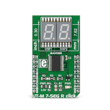
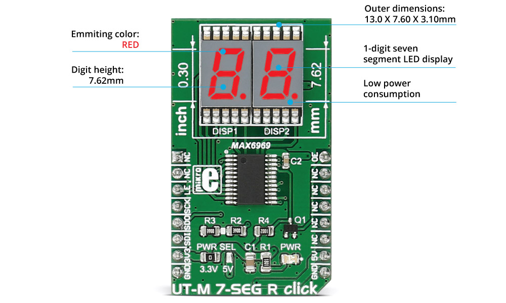
매우 얇은 7-Seg 디스플레이 모듈 -빨강, 7.62mm 크기
(UT-M 7-SEG R click)

개요
특징
-
How the click works
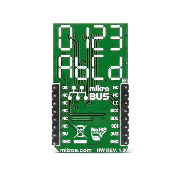
The 7 segment displays are interfaced to the MCU over the MAX6969 16-port, constant-current LED driver IC.
It uses the common 4-wire serial bus for communication with the MCU itself (LE, SCK, SDO, SDI on mikroBUS™ pin socket).
There is an additional OE (output enable) pin which is used to control the output driver state (enabled/disabled). Since it is the PWM output pin on the mikroBUS™ by default, the LED segments light intensity could be controlled by software too.
MAX6969 driver features
The MAX6969 uses the industry-standard, shift-register-plus-latch-type serial interface.
The driver accepts data shifted into a 16-bit shift register using data input DIN and clock input CLK. Input data appears at the DOUT output 16 clock cycles later to allow cascading of multiple MAX6969s. So, the IC allows you to connect multiple click boards™ - for applications that require more than two seven segment displays, such as digital clocks, temperature sensors, etc.Specifications
Type LED Segment Applications Displaying digits and letters on two 7 segment displays Displays Ultra thin (3.1mm) LED 7-SEG displays in RED emitting color On-board modules MAX6969 6-Port, 5.5V Constant-Current LED Driver Key Features Excellent character appearance, low power consumption Interface SPI Input Voltage 3.3V or 5V Click board size M (42.9 x 25.4 mm) Pinout diagram
This table shows how the pinout on UT-M 7-SEG R click corresponds to the pinout on the mikroBUS™ socket (the latter shown in the two middle columns).
Notes Pin 
Pin Notes NC 1 AN PWM 16 OE PWM control of light intensity NC 2 RST INT 15 NC Load-Enable input LE 3 CS TX 14 NC Clock input SCK 4 SCK RX 13 NC Serial Data Output SDO 5 MISO SCL 12 NC Serial Data Input SDI 6 MOSI SDA 11 NC Power supply +3.3V 7 3.3V 5V 10 +5V Power supply Ground GND 8 GND GND 9 GND Ground Jumpers and settings
Designator Name Default Position Default Option Description JP1 PRW.SEL. Left 3V3 Power Supply Voltage Selection 3V3/5V, left position 3V3, right position 5V
문서
연관제품
- 연관제품 1


