


 수량을 선택해주세요.


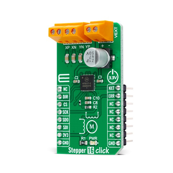
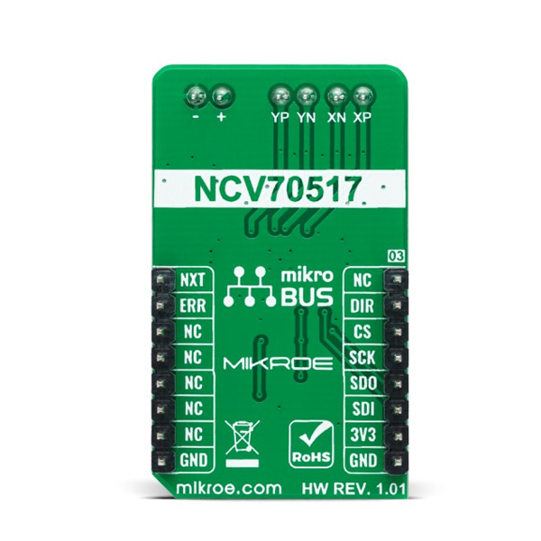
스텝모터 드라이버 -NCV70517
(STEPPER 16 CLICK)
개요
- 본 제품은 스텝모터 드라이버 -NCV70517입니다.
- SPI 및 I/O로 설정이 가능한 바이폴라 스텝 모터 드라이버 NCV70517 칩을 장착하고 있습니다.
- SPI 인터페이스를 가지고 있으며, 3.3V 시스템과 동작이 가능합니다.
특징
-
Type Stepper Applications Can be used for general−purpose stepper motor applications in the automotive, industrial, and applications with fluctuating battery supplies. On-board modules NCV70517 - integrated motor-driver solution for bipolar stepper motors with integrated current sense and current regulation from ON Semiconductor Key Features Dual H−bridge for 2−phase stepper motors, fully integrated current−sensing and current−regulation, integrated current translator, 5 step modes from full-step up to 16 micro-steps, PWM current control with automatic selection of fast and slow decay, and more Interface GPIO,SPI Compatibility mikroBUS Click board size M (42.9 x 25.4 mm) Input Voltage 3.3V,External -
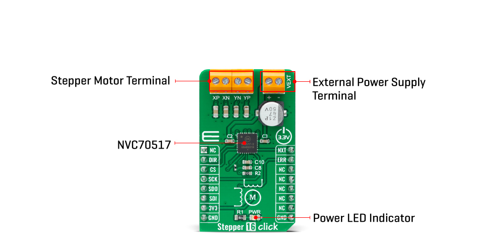
Stepper 16 Click as its foundation uses the NCV70517, an integrated motor-driver solution for bipolar stepper motors with integrated current sense and current regulation from ON Semiconductor. Two H−bridges are integrated to drive a bipolar stepper motor with a PWM current control loop with on-chip current sensing implemented for each H−bridge. It provides complete output protection, overcurrent protection, and thermal warning and shutdown, alongside with proprietary PWM algorithm used for reliable, current control allowing automatic selection of fast and slow decay.
The NCV70517 communicates with MCU using the standard SPI serial interface with a maximum frequency of 10MHz. One of five possible stepping modes is selectable through bits of the SPI registers. After Power−On or hard reset, the coil−current translator, which translates consecutive steps into corresponding currents in both motor coils for a given step mode, is set to the default to 1/16 micro−stepping at position '8'. Besides the micro−step modes, full step mode is implemented, which always activates only one coil.
The direction of rotation is selected by input pin DIR routed to the RST pin of the mikroBUS™ socket and its polarity bit DIRP, which allows changing the direction of rotation through only SPI commands instead of the dedicated input pin. Besides, it also takes the next micro−step depending on the clock signal on the NXT input pin routed to the PWM pin of the mikroBUS™ socket and provides an error message on the ERR pin routed to the INT pin of the mikroBUS™ socket if an electrical error, an undervoltage, or an elevated junction temperature is detected.
This Click board™ supports an external power supply for the motor, which can be connected to the input terminal labeled as VEXT and should be within the range of 6V to 29V, while the stepper motor coils can be connected to the terminals labeled as XP, XN, YP, and YN.
This Click board™ can be operated only with a 3.3V logic voltage level. Therefore, the board must perform appropriate logic voltage level conversion before using MCUs with different logic levels. However, the Click board™ comes equipped with a library containing functions and an example code that can be used, as a reference, for further development.


