


 수량을 선택해주세요.


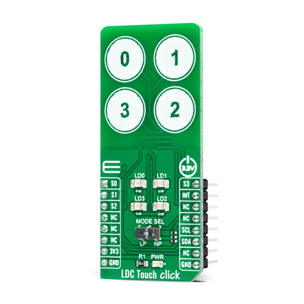
4채널 터치 센서 -LDC3114-Q1
(LDC TOUCH CLICK)
개요
- 본 제품은 4채널 터치 센서 -LDC3114-Q1입니다.
- 인덕턴스-디지털 변환칩 LDC3114-Q1 을 기반으로 디자인된 제품으로 저전력 근접 센싱 및 터치버튼 센싱 기능을 가지고 있습니다.
- I2C 인터페이스를 가지고 있으며, 3.3V 시스템과 사용이 가능합니다.
특징
-
LDC Touch Click as its foundation uses the LDC3114-Q1, a hybrid multichannel, high-resolution inductance-to-digital converter from Texas Instruments. This inductive sensing device enables touch button design for a human-machine interface (HMI) by measuring small deflections of conductive targets using a coil implemented on a printed circuit board. Button presses form micro-deflection in the conductive targets, which cause frequency shifts in the resonant sensors, and measures such frequency shifts determining when button press occurs. With adjustable sensitivity per input channel, the LDC3114-Q1 can reliably operate with a wide range of physical button structures and materials.
The LDC3114-Q1 offers two main modes of operations: raw data access mode and button algorithm mode, which is controlled by register settings. The button mode can automatically correct any deformation in the conductive targets and offers well-matched channels allowing for differential and ratiometric measurements, which enable compensation of environmental and aging conditions such as temperature and mechanical drift. On the other hand, it also implements a raw data access mode, where MCU can read directly the data representing the effective inductance of the sensor and implement further post-processing.
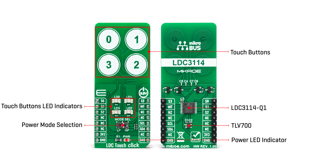
This Click board™ communicates with MCU using the standard I2C 2-Wire interface to read data and configure settings, supporting a Fast Mode operation up to 400kHz. Also, the LDC3114-Q1 requires a voltage of 1.8V for its power supply to work correctly. Therefore, a small regulating LDO, the TLV700, provides a 1.8V out of 3V3 mikroBUS™ power rail.
As mentioned earlier, this board contains four touch buttons, representing the only elements on the upper-top side of the board. Each of these buttons has its own LED indicator representing the activity in that field. If a touch event is detected on one of these onboard pads, the state of the corresponding LED will be changed, indicating an activated channel; more precisely, touch has been detected on that specific field.
Alongside LED indicators, data from these channels can be processed via the MCU through four pins labeled from S0 to S3, routed to the AN, RST, CS, and PWM pin of the mikroBUS™ socket, respectively. Besides, there is an additional interrupt signal routed on the INT pin of the mikroBUS™ socket indicating when a specific interrupt event occurs (touch detection, available new data, and such), alongside two power modes of operation. A Normal Power Mode for active sampling at 10, 20, 40, or 80SPS, and a Low Power Mode for reduced current consumption at 0.625, 1.25, 2.5, or 5SPS selectable through an onboard switch labeled as MODE SEL.
This Click board™ can be operated only with a 3.3V logic voltage level. The board must perform appropriate logic voltage level conversion before using MCUs with different logic levels. However, the Click board™ comes equipped with a library containing functions and an example code that can be used, as a reference, for further development.
SPECIFICATIONS
Type Inductance Applications Can be used for human-machine interface and precise linear position sensing of metal targets for automotive, consumer, and industrial applications On-board modules LDC3114-Q1 - hybrid multichannel, high-resolution inductance-to-digital converter from Texas Instruments Key Features AEC-Q100 qualified, multiple modes of operation, configurable scan rates, advanced button press detection algorithms, low power consumption, and more Interface I2C Compatibility mikroBUS Click board size L (57.15 x 25.4 mm) Input Voltage 3.3V
문서
연관제품
- 연관제품 1


