


 수량을 선택해주세요.


CH551G 개발 보드 -SOP16 USB 마이크로컨트롤러
(CH551G Development board - SOP16 USB microcontroller)

개요
- 본 제품은 CH551G 개발 보드 -SOP16 USB 마이크로컨트롤러입니다.
- MCS51 인스트럭션 세트와 호환되는 e8051 코어 싱글 칩인 CH551G 칩을 기반으로 디자인된 제품입니다.
- 4개 채널의 정전식 터치 버튼, 세개의 타이머, PWM, SPI, UART 등을 지원합니다.
특징
- Core: enhanced e8051 core, compatible with MCS51 instruction set. 79% of its instructions are single byte single cycle instructions. The average instruction speed is 8-15 times faster than the standard MCS51. It has a special xram data replication instruction and double dptr pointer.
- ROM: 10 KB capacity of multi programmable non-volatile memory ROM, can be used for all program storage space
- Data Flash: 128 bytes multi erasable non-volatile data memory, which supports rewriting data in bytes.
- RAM: 256 bytes internal RAM, which can be used for fast data storage and stack; 512 bytes on chip xram can be used for large amount of data temporary storage and DMA (direct memory access).
- USB: embedded USB controller and USB transceiver, supporting USB device mode, master-slave detection, supporting USB 2.0 full speed 12mbps or low-speed 1.5mbps. FIFO is built-in and supports 64 bytes of data packets.
- Timer: three groups of timers, t0 / T1 / T2 is the standard MCS51 timer.
- Capture: timer T2 is extended to support 2-way signal capture.
- PWM: 2 sets of PWM output, pwm1 / pwm2 is 2-way 8-bit PWM output.
- UART: asynchronous serial port, support higher communication baud rate, UART0 is the standard MCS51 serial port.
- SPI: SPI controller has built-in FIFO, clock frequency up to half of the system's main frequency Fsys, supports serial data input and output simplex multiplexing, and supports master / slave mode.
- Touch key: 4-channel capacitance detection, support independent timing interrupt.
- GPIO: supports up to 17 GPIO pins (including Xi / XO, RST and USB signal pins).
- Interrupt: supports 14 groups of interrupt signal sources, including 6 groups of interrupts (INT0, T0, INT1, T1, etc.) compatible with standard MCS51 UART0, T2), and extended 8 groups of interrupts (spi0, tkey, USB, ADC, uart1, pwmx, GPIO, wdog), in which GPIO interrupt can be selected from 7 pins.
- Watch dog: 8 bits can preset watchdog timer wdog, support timing interrupt.
- Reset: support 4 kinds of reset signal source, built-in power on reset, support software reset and watchdog overflow reset, optional pin external input reset.
- Clock: built in 24 MHz clock source, which can support external crystal by multiplexing GPIO pins.
- Power: built in 5V to 3.3V low voltage differential voltage regulator, supporting 5V or 3.3V or even 2.8V power supply voltage. It supports low-power sleep, USB, UART0, uart1, spi0 and part of GPIO external wake-up.
- The chip has a unique ID number.
-
CH551G development board features the CH551 chip, which is an enhanced e8051 core single-chip microcomputer compatible with MCS51 instruction set. 79% of its instructions are single-byte single-cycle instructions, and the average instruction speed is 8-15 times faster than the standard MCS51.
Ch551 supports up to 24MHz system main frequency. It has built-in 10KB program memory (ROM), 256-byte internal IRAM, and 512 bytes on-chip xram. Xram supports DMA (direct memory access).
The ch551 has 4 channel capacitive touch buttons, three sets of timers and signal capture, PWM, SPI, asynchronous serial port (UART0), USB device controller, and full speed transceiver.
문서
-
How to Flash Bootloader?
- Open WCHISPTool_Setup file
- Press and hold the BL button on the development board and connect the USB cable to the PC
- Select "8-bit CH55x series from the top menu
- Select CH551 as the chip mode
- Check the boxes: "Run the target program after download complete", "Clear DataFlash"
- Select the file you want to download under "User File"
- Click the "Download" button
Hardware Overview
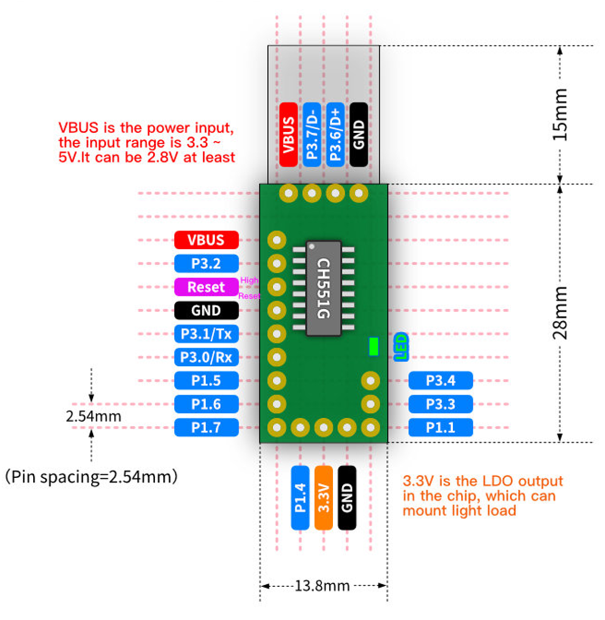
-


