


 수량을 선택해주세요.


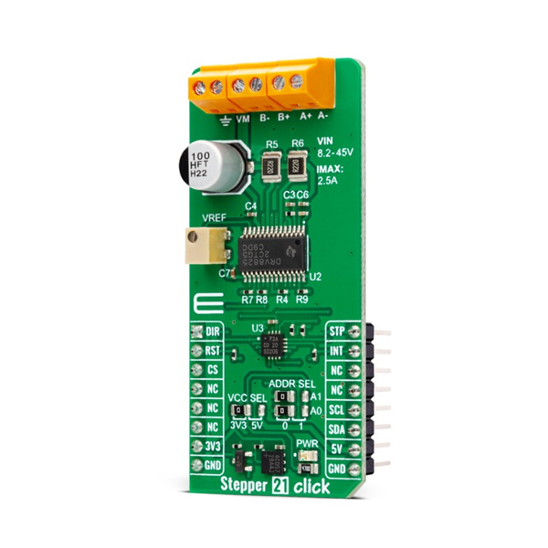
바이폴라 스텝 모터 드라이버 -DRV8825
(STEPPER 21 CLICK)
개요
- 본 제품은 바이폴라 스텝 모터 드라이버 -DRV8825 입니다.
- PWM 마이크로 스텝핑 스텝모터 드라이버 DRV8825 칩을 탑재하고 있으며, 8.2V-45V의 동작전압을 가지고 있습니다.
특징
-
HOW DOES IT WORK?
Stepper 21 Click is based on the DRV8825, a stepper motor controller integral circuit from Texas Instruments. By integrating two NMOS H-bridges, current sense, and a STEP/DIR interface, the DRV8825 allows easy interfacing with the controller circuit. The STEP/DIR interface provides a simple method for advancing through the indexer table, with the direction determined by the DIR input pin and the indexer traveling for each rising edge on the STEP input pin. It uses three decay modes of operation, fast, slow, and mixed decay, as a highly configurable current regulation. Additional features are overcurrent protection, thermal shutdown, supply voltage undervoltage lockout, and fault condition indication.
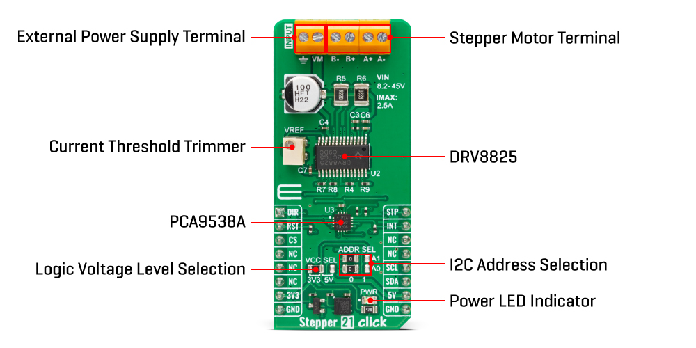
The host MCU can control the direction and steps of the stepper driver directly through the DIR and STP pins of the mikroBUS™ socket. As a feature of its own, the Stepper 21 Click comes with a VREF potentiometer to set a reference voltage for winding current on both A and B bridges. The Stepper 21 Click also uses the PCA9538A, a low-voltage 8-bit I/O port expander from NXP Semiconductors, and its standard 2-Wire interface to communicate with the host MCU and control some of the features of the stepper driver.
The PCA9538A provides a flexible set of GPIOs, contains an 8-bit register set, and is necessary for interfacing the DRV8825 control pins to the host MUC over the pins-limited mikroBUS™ socket. Besides the standard 2-Wire interface, the host MCU has access to the expander's reset and interrupt lines over the RST and INT pins of the mikroBUS™ socket. The interrupt output is activated when any input state differs from its corresponding input port register state. The I2C address of the expander can be selected over the ADDR SEL jumper with 0 set by default.
The expander can also control other features like Sleep mode, home position indication, decay mode selection, fault indicator triggered by over-temperature and over-current protection, or allow you to enable or disable the stepper driver. Last but not least, the expander controls micro-step modes combination (Mode 0-2), thus allowing the selection of full, 1/2, 1/4, 1/8, 1/16, and 1/32 steps.
The Stepper 21 Click supports an external power supply for the DRV8825, which can be connected to the input terminal labeled as INPUT VM and should be within the range of 8.2V to 45V (2.5A), while the stepper motor coils can be connected to the terminals labeled as B+, B-, A-, and A+.
This Click board™ can operate with either 3.3V or 5V logic voltage levels selected via the VCC SEL jumper. This way, both 3.3V and 5V capable MCUs can use the communication lines properly. However, the Click board™ comes equipped with a library containing easy-to-use functions and an example code that can be used, as a reference, for further development.
SPECIFICATIONS
Type Stepper Applications Can be used for small stepping motors in various applications such as office automation and commercial and industrial equipment On-board modules DRV8825 - stepper motor controller integral circuit from Texas Instruments Key Features Low power consumption, capable of controlling the bipolar stepping motor, operational in full, half, quarter, 1/8, 1/16, and 1/32 step resolutions, built-in a mixed decay mode, anomaly detection functions, expander that controls most of I/O of the stepper driver with interrupt abilities, and more Interface GPIO,I2C Compatibility mikroBUS Click board size L (57.15 x 25.4 mm) Input Voltage 3.3V or 5V


