


 수량을 선택해주세요.


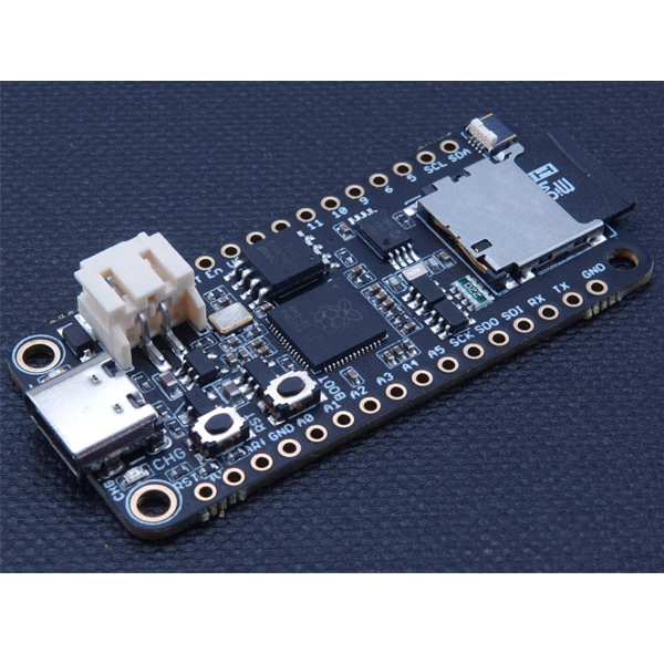
RP2040 SD/RTC 보드 - microSD, MCP79410
(Challenger RP2040 SD/RTC)
개요
- 본 제품은 RP2040 SD/RTC 보드 - microSD, MCP79410입니다.
- 아두이노/CircuitPython 개발환경의 피더 보드 포맷의 마이크로컨트롤러 보드로 RP2040 칩 및 RTC MCP79410 칩과 micrSD 슬롯을 장착하고 있습니다.
- USB C 커넥터를 장착하고 있으며, 배터리 연결을 위한 JST PH 커넥터와 배터리 충전 회로를 지원합니다.
특징
-
Micro SD Card
This board is equipped with a micro SD card connector that will house standard micro SD cards allowing your application to have many gigabytes of storage room for sensor data or what ever you want to place on it. Together with a fancy display you could also store cool images.
Real Time Clock (RTC)
It is normally very useful to tag sensor data with a time stamp so we included a Real Time Clock chip to make this easy for you.
The chip we use is the MCP79410 general purpose I2C™Compatible real-time clock/calendar. It is a highly integrated real time clock with nonvolatile memory and many other advanced features. These features include a battery switchover circuit for backup power, a timestamp to log power failures and digital trimming for accuracy. Using a low-cost 32.768 kHz crystal or other clock source, time is tracked in either a 12-hour or 24-hour format with an AM/PM indicator and timing to the second, minute, hour, day of the week, day, month and year. As an interrupt or wakeup signal, a multifunction open drain output can be programmed as an Alarm Out or as a Clock Out that supports 4 selectable frequencies.
The intperrupt output from the RTC is connected to pin GPIO25 on the RP2040 and can be used to wake up the device repeatedly to collect data.
USB Type C
In the recent years we have noticed that we are seeing more and more USB Type C cable laying around the lab due to the fact that all new phones and accessories use them. As of yet we haven't seen any shortage of micro USB cables but we are not getting any new ones any more and old ones do break occasionally. So we decided to go for a USB Type C connector for this board. A bonus of this is that they are quite bit more durable and you don't have to fiddle with the cable when plugging it in.
On board charger
The board is equipped with a standard 2.0mm JST connector for connecting a rechargeable LiPo battery. There is also an internal battery charger circuit that charges your battery as long as a USB cable is inserted or the VUSB connection is connected to 5V.
문서
-
Datasheet
Click here to read the detailed datasheet.
Note
The SD Card is not included with the board and needs to be purchased separately.
- Github page
- The Challenger RP2040 WiFi board is fully compatible with both the micropython package found at the Raspberry Pi site as well as Adafruits CircuitPython. Instruction are available on how to install the python interpreter of your choice is available on respective web site.
- Datasheet
- RunCPM image including HW I/O port support.
- CPM File image for RunCPM
- Getting started with RunCPM for the Challenger RP2040 SD/RTC board
- CircuitPython download page
연관제품
- 연관제품 1


