


 수량을 선택해주세요.


TPS2113A 파워멀티플렉서 -microB USB 커넥터
(TPS2113A Power Multiplexer Carrier
with USB Micro-B Connector)


개요
- 본 제품은 TI사의 TPS2113A을 탑재한 오토스위칭 파워 멀티플렉서입니다.
- 부하에 연결되어 있는 두개의 전력 소스중 하나를 선택할 수 있게 하여주면서 양 전력 소스로 역전류가 흐르는 것을 방지하여 줍니다.
- 최대 2A 설정할 수 있는 조절가능한 전류 제한 기능 및 조절가능한 스위칭 스레쉬홀드를 가지고 있습니다.
- 멀티플렉서의 각 입력 파워 레일에는 2.8V에서 5.5V를 공급할 수 있습니다.
- 보드상에는 microB USB 커넥터가 장착되어 있으며, 파워 입력중 하나로 사용할 수 있습니다.
- TPS2113A는 디폴트로 오토 스위칭 모드로 동작합니다. 다시 말하면 공급되는 전압중 높은 전압으로 자동 선택합니다.
- 하지만 VSNS핀과 설정가능한 스위칭 스레쉬홀드값을 이용하여 IN1을 입력으로 유지할 수도 있습니다.
- 보드는 USB 파워가 기본으로 IN1에 연결되어 있습니다.
특징
-
Minimum operating voltage: 2.8 V3 Maximum operating voltage: 5.5 V Maximum output current: 2 A -
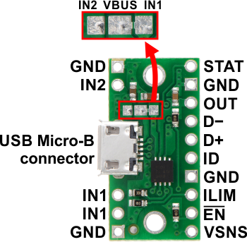
Pin Description IN1 Primary power switch input. Can be connected to a 2.8 V to 5.5 V power source. Connected to VBUS by default through surface-mount jumper. The multiplexer will function with IN1 as low as 1.5V as long as IN2 is above 2.8 V. IN2 Secondary power switch input. Can be connected to a 2.8 V to 5.5 V power source. VBUS USB 5 V supply. Connected to IN1 by default through surface-mount jumper. OUT Multiplexed power output. GND Common ground for power supplies, load, and USB. (All of the board's GND pins are internally connected with each other and with GND from the USB connector.) VSNS Switching control input. An internal power FET connects OUT to IN1 if the VSNS voltage is greater than 0.8 V. Otherwise, the FET connects OUT to the higher of IN1 and IN2. This pin is pulled low through an on-board 20 kΩ pull-down resistor, setting the board to autoswitching mode by default. See the Control inputs section below for more details on using this pin to set a switching threshold. EN Enable input. When driven high, OUT is disconnected from both IN1 and IN2. This pin is pulled low through an on-board 100 kΩ pull-down resistor so the IC is enabled by default. ILIM Current limit input. An on-board 1 kΩ resistor from ILIM to GND sets the default current limit to 0.5 A nominally, but an external resistor can be added in parallel with it to increase the limit to a maximum of 2 A. STAT Status output that indicates which input is currently connected to the output. This pin drives low when IN1 is selected and is pulled up to OUT through an on-board 100 kΩ pull-up resistor when IN2 is selected. D−
D+
IDSignals broken out from USB connector.
문서
- TPS2113A power multiplexer carrier with USB Micro-B connector schematic diagram (171k pdf)
- TPS2113A datasheet (1MB pdf)
- New product: TPS2113A Power Multiplexer Carrier with USB Micro-B Connector by Kevin - 20 June 2014
- Product Page


