수량을 선택해주세요.


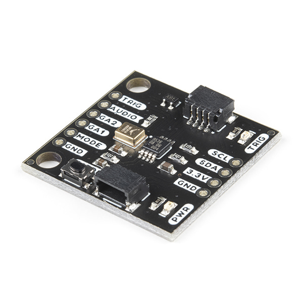
I2C 사운드 트리거 모듈 -VM1010
(Qwiic Sound Trigger)
개요
- 본 제품은 I2C 사운드 트리거 모듈 -VM1010 입니다.
- VM1010 칩을 기반으로 디자인된 제품으로 소리를 검출하면 깨어나서 TRIG(DOUT) 핀을 HIGH 상태로 만듭니다.
- 그런 다음 MODE 핀을 low로 하면 Normal 모드로 들어가게 되며 일반적인 마이크포폰 기능을 하게 됩니다.
- 아날로그 마이크로폰 신호는 AUDIO(VOUT)핀에서 접근이 가능합니다.
특징
- Vesper Technologies VM1010
- Piezoelectric MEMS microphone
- ZeroPower ListeningTM: 300Hz - 6kHz
- Min Acoustic Threshold: 65 dB SPL
- Max Acoustic Threshold: 89 dB SPL
- Start-up time: 50 microseconds
- Dust and water resistant to IP57
- Operating Temperature Range: -40 to +85 °C
- Supply Voltage: 1.6VMin, 1.8VTyp, 3.6VMax
- PCA9536 GPIO expander
- I2C address: 0x41
- Supply Voltage: 2.3VMin, 5.5VMax
- Note: Qwiic bus operates at 3.3VMax
- Breakout pads for:
- I2C
- DOUT / Trigger
- MODE / Reset
- Gain adjustment
- Analog audio output
- VOUT bias is 0.8V
- Power LED
- Trigger LED
-
The Qwiic Sound Trigger is based on the VM1010 from Vesper Technologies and the TI PCA9536 GPIO expander.
The VM1010 is a clever little device which can be placed into a very low power "Wake On Sound" mode. When it detects a sound, it wakes up and pulls its TRIG (DOUT) pin high. The VM1010 can then be placed into "Normal" mode by pulling the MODE pin low; it then functions as a regular microphone. The analog microphone signal is available on the AUDIO (VOUT) pin. All of this happens really quickly, within 50 microseconds (much faster than a capacitive MEMS microphone), so you don't miss the start of the audio signal.
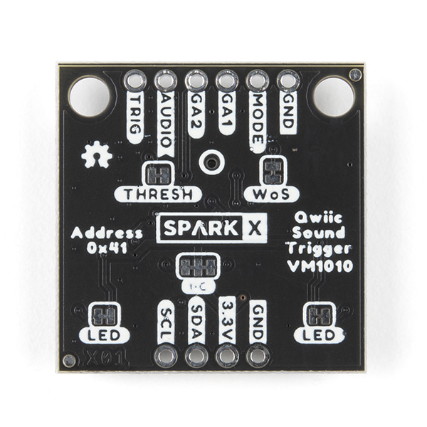
The noise threshold required to wake the VM1010 can be programmed via the resistance between pins GA1 and GA2. By default, the 20K resistor on the breakout sets the noise threshold to close to the minimum (most sensitive) setting. You can increase the threshold to maximum (least sensitive) by cutting the THRESH jumper. You can set it mid-way by adding your own resistor between breakout pins GA1 and GA2.
If you are using the VM1010 purely as a sound trigger, you need to reset it after each event by: pushing the MODE button; pulling the MODE breakout pin low; or using the Qwiic bus to instruct the PCA9536 to pull the MODE signal low (the VM1010 MODE signal is connected to GPIO0).
You can use the TRIG (DOUT) breakout pin to generate an interrupt on your microcontroller. Or you can read (poll) its state via the PCA9536 (the TRIG (DOUT) signal is connected to GPIO1).
There are two LEDs: one to indicate if the breakout is powered; and a second to show when a sound trigger has taken place. You can disable either or both LEDs to save power by cutting the LED jumpers on the back of the breakout.
As usual, the breakout includes I2C pull-up resistors. You can disable those if you need to by cutting the I2C jumpers.
Our GitHub Repo contains two example sketches for the Arduino IDE:
- Example1 is a very simple example showing how to read the sound trigger TRIG signal via the PCA9536 GPIO1 pin and reset it via the MODE signal and GPIO2
- Example2 is a more complex example showing how you can capture and log the rising edge of the sound event with nanosecond resolution using a ZED-F9P GNSS receiver
The Repo also contains Python code, described in our tutorials, which you can use to calculate the location of a sound in 1D or 2D!


 "19세 미만의 미성년자"는 출입을 금합니다!