


 수량을 선택해주세요.


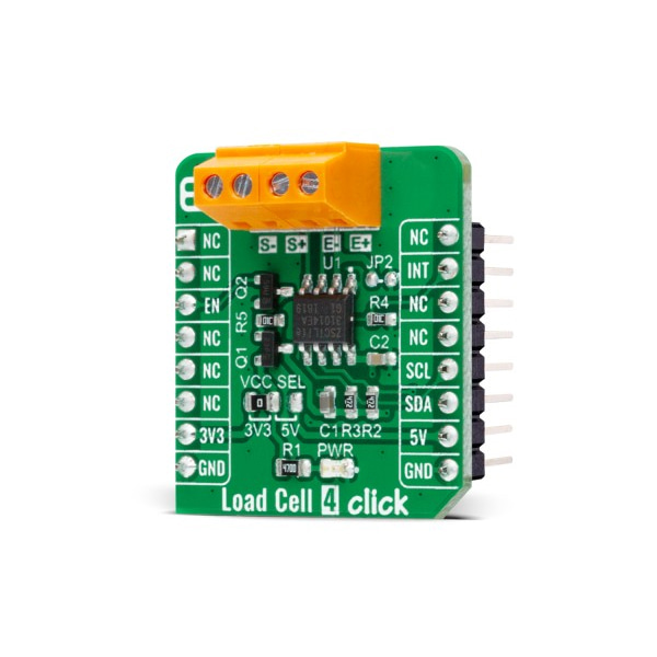
로드셀 앰프 모듈 -ZSC31014
(LOAD CELL 4 CLICK)
개요
- 본 제품은 로드셀 앰프 모듈 -ZSC31014입니다.
- ZSC31014 칩 기반으로 디자인된 제품으로 차동 및 half-bridge 입력 신호를 디지털로 변환하여 줍니다.
- 로드셀과 연결하여 사용이 가능하며, I2C 인터페이스를 가지고 있습니다.
특징
-
Type Force Applications Can be used for safety-critical and weight measurement applications. On-board modules Load Cell 4 Click is based on the ZSC31014, a CMOS integrated circuit for highly accurate amplification and analog-to-digital conversion of differential and half-bridge input signals from Renesas. Key Features High accuracy, digital compensation of sensor offset, sensitivity,temperature drift, and non-linearity, eight programmable analog gain settings, internal temperature compensation for sensor correction and for corrected temperature output, and more. Interface I2C Compatibility mikroBUS Click board size S (28.6 x 25.4 mm) Input Voltage 3.3V or 5V -
Load Cell 4 Click is based on the ZSC31014, a CMOS integrated circuit for highly accurate amplification and analog-to-digital conversion of differential and half-bridge input signals from Renesas. The ZSC31014 has a fully differential chopper-stabilized preamplifier with 8 programmable gain settings (1.5, 3, 6, 12, 24, 48, 96, and 192) through a 14-bit ADC. The resolution of the output depends on the input span and the analog gain setting. The system clock of the ZSC31014 can operate at 1MHz (lower power, better noise performance) or at 4MHz (faster sample rates). Internal DSP core uses coefficients stored in EEPROM to precisely calibrate/condition the amplified differential input signal. Temperature can be measured from an internal temperature sensor, which can be calibrated to compensate for the temperature effects of the sensor bridge.
.jpg)
After the Power-On Reset function, the ZSC31014 wakes, and if it receives the Start_CM command during the command window, it goes into Command Mode. This Mode is primarily used in the calibration environment, and during Command Mode, the device executes commands sent by the I2C master. The ZSC31014 remains in Command Mode until it receives the Start_NOM command, which starts the Normal Operation Mode. Operation after the Power-On sequence depends on whether the part is programmed in Sleep Mode or Update Mode. In Sleep Mode, the ZSC31014 waits for commands from the master before taking measurements, while in Update Mode, data is taken at a fixed, selectable rate.
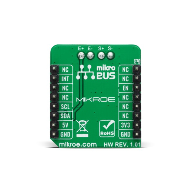
Load Cell 4 Click communicates with MCU using the standard I2C 2-Wire interface with a clock frequency from 100 up to 400 kHz. The INT pin of the mikroBUS™ socket, used as an interrupt, rises when new output data is ready and falls when the next I2C communication occurs. It is most useful if the part is configured in Sleep Mode to indicate to the system that a new conversion is ready. Besides, this Click board™ also possesses an Enable pin labeled as EN, routed to the CS pin of the mikroBUS™ socket, which serves to turn the ZSC31014's power supply on/off.
This Click board™ is designed to operate with both 3.3V and 5V logic voltage levels selected via the VCC SEL jumper. It allows for both 3.3V and 5V capable MCUs to use the I2C communication lines properly. However, the Click board™ comes equipped with a library that contains functions and an example code that can be used, as a reference, for further development.


