


 수량을 선택해주세요.


솔리스 스테이트 파워 스위치 -역전압보호, 4.5V-40V, 16A, 대형 푸쉬버튼
(Big Pushbutton Power Switch with Reverse Voltage
Protection, HP)


개요
- 본 제품은 솔리스 스테이트 파워 스위치 -역전압보호, 4.5V-40V, 16A, 대형 푸쉬버튼 입니다.
- solid state 파워 스위치로 역전압 보호기능을 내장하고 있으며, 순간 푸쉬버튼으로 제어됩니다.
- 대형 기계식 스위치를 대치하여 정교하게 전원을 제어할 수 있는 스위치로 래치 타입입니다.
- 한번 누르면 on, 다시한번 누르면 off가 되게 됩니다.
특징
-
Current rating: 16 A2 Minimum operating voltage: 4.5 V Maximum operating voltage: 40 V3 Reverse voltage protection?: Y - The Pololu Pushbutton Power Switches are sophisticated power control alternatives to bulky mechanical switches. The main function is pushbutton-based latching power control, where one push turns on power and another push turns it off. Additional control inputs allow advanced applications such as automatic shutdown by the device being powered. This HP version operates from 4.5 V to 40 V and can deliver continuous currents up to around 16 A.
-
The Pololu Pushbutton Power Switch is a compact, solid-state power switch that features built-in reverse-voltage protection and is controlled by a momentary pushbutton: one push turns on power and another push turns it off. This is a patented design initially created for use in our own products as an alternative to bulky mechanical switches. Because the switched current does not flow through the mechanical switch, a large variety of small, low-power switches can be used to control a substantial amount of power. The use of momentary switches also allows multiple switches to be used in parallel to control the power to one load.
The board has a small pushbutton already installed and offers convenient points for connecting external pushbutton or tactile switches in parallel. It also offers several alternate pushbutton connection options that result in push-on-only or push-off-only operation, and additional inputs enable further power control options like allowing the load to turn off its own power, which can be beneficial when used with battery chemistries sensitive to over-discharging.
Warning: Do not use this switch as an emergency cutoff or similar safety disconnect in applications where failure to cut power could lead to injury or property damage.
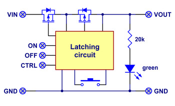

Block diagram of the Big Pushbutton Power Switch with Reverse Voltage Protection. The switch and control inputs control the state of a latching circuit that in turn controls a pair of power MOSFETs through which the main current flows. Four versions of the Pololu Pushbutton Power Switches are available:
- Mini Pushbutton Power Switch LV
- Mini Pushbutton Power Switch SV
- Big Pushbutton Power Switch MP
- Big Pushbutton Power Switch HP
The two Mini Pushbutton Power Switches are smaller, lower-current versions that are useful for applications with tight size constraints or lower power requirements. Also, the the Mini LV is the only one of the four that works below 4.5 V; since it can operate down to 2.2 V, this version can be used with a single lithium cell battery.
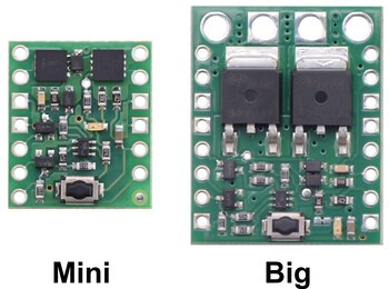
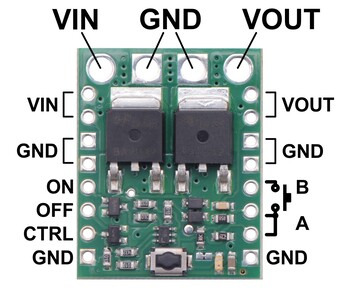
The pinout of the Big version is the same as the pinout of the Mini version with several additional redundant connection points for convenience, including main power connections that are compatible with 5 mm terminal blocks.
The primary functional difference between the each of the units arises from the MOSFET used, which sets the operating range and performance of the units:
LV
SV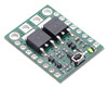
MP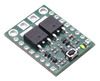
HPAbsolute max voltage: 20 V 40 V Recommended operating voltage: 2.2 V to 16 V 4.5 V to 32 V MOSFET combined on resistance (max) 26 mΩ @ 1.8 V 16 mΩ @ 4.5 V 90 mΩ @ 4.5 V 40 mΩ @ 4.5 V 13 mΩ @ 4.5 V 50 mΩ @ 10 V 30 mΩ @ 10 V 8.6 mΩ @ 10 V Continuous current at 55°C(1) 3.0 A 2.0 A 4.0 A 6.0 A Continuous current at 150°C(1) 6.0 A 4.3 A 8.0 A 16 A Maximum current 12 A 7.2 A 40 A 90 A Current consumption in on state(2) ~210 μA/V ~120 μA/V Current consumption in off state ~0.01 μA < 0.01 μA < 0.01 μA < 0.2 μA LED color red green Size 0.6″ × 0.7″ × 0.12″ 0.8″ × 1.0″ × 0.16″ Weight 0.6 g 2.7 g 1 At 12 V with ambient temperature of 22°C in still air.
2 On state current is dominated by indicator LED; current is approximately proportional to input voltage.
Please note that this switch has several drawbacks when compared to mechanical switches, so please be sure you fully understand this product before using it in your system.
Compared to the previous versions of the Pololu pushbutton power switches, the new versions have substantially expanded operating voltage ranges along with reverse-voltage protection and more control options. The size and pinout has changed, so the new versions cannot be used as direct drop-in replacements for the old ones.
Benefits and limitations
The Pololu Pushbutton Power Switch works well in its intended application as a DC power switch for small robots, but because it is fundamentally different from a mechanical power switch, the benefits and drawbacks of the components must be fully considered.
Benefits over mechanical switches:
- Compact size
- Reverse-voltage protection
- Allows multiple (parallel) switches for improved user interface
- Better turn-on characteristics than a bouncing mechanical switch
- Limited LC spikes for low-resistance loads
- Allows self-shutoff (OFF input)
- Allows external digital device to control the power state (ON and CTRL inputs)
- Breadboard and perfboard compatible (0.1″-pitch)
Drawbacks compared to mechanical switches:
- Switch is one-directional (power applied to VOUT cannot be switched to VIN)
- Limited operating voltage range
- Switch can lose its state when power is disconnected (the switch typically defaults to being off when power is first applied, but it can default to being on near the upper end of the operating range)
- Switches DC only (does not maintain state through power disruptions or excessive noise)
- No complete isolation in off state
We also offer a MOSFET Slide Switch with Reverse Voltage Protection that avoids several of these drawbacks.
Using the Pushbutton Power Switch
The simplest way to control the Pushbutton Power Switch is via its installed pushbutton: one push turns on power and another turns it off. Alternatively, a separate pushbutton, such as a remote panel-mounted unit, can be connected to the A and B pins and used instead. Multiple pushbuttons can be wired in parallel for multiple control points, and each of the parallel pushbuttons, including the one on the board itself, will be able to turn the switch on or off. The latching circuit performs some button debouncing, but pushbuttons with excessive bouncing (several ms) might not function well with this product.
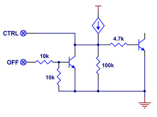
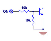
More advanced control options are available through the button connection pins and three control inputs:
PIN Description A Connect through momentary switch to pin "B" for standard push-on/push-off operation. Connect through momentary switch to ground for on-only operation. B Connect through momentary switch to pin "A" for standard push-on/push-off operation. ON A high pulse (> 1 V) on this pin turns on the switch. OFF A high pulse (> 1 V) on this pin turns off the switch (e.g. allowing the target device to shut off its own power). CTRL This pin directly determines the state of the switch. A high pulse (> 1 V) on this pin turns on the switch; a low pulse (e.g. driving the pin low with a microcontroller output line or pushing a button connected from this pin to ground) turns the switch off. Leave this pin disconnected or floating when not trying to set the switch state. Note that this pin should not be driven high at the same time the "OFF" pin is driven high. The input structures for the three control inputs are shown below:
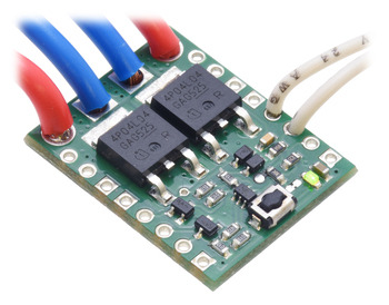
Each power node can be accessed through a large hole along the top side of the board or two smaller 0.1″-spaced holes along the sides of the board. For applications drawing more than 5 A, you should either use the large holes or both 0.1″-spaced holes for each power connection.
Included Hardware
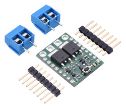
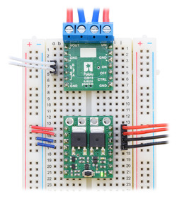
Two 8-pin straight breakaway male headers and two 2-pin 5mm terminal blocks are included with each switch, and you can choose which of these components, if any, to solder to the board. The terminal blocks work with the four large holes, and the header strips allow the switch to be used withsolderless breadboards and perforated circuit boards with standard 0.1″ spacing. If you want to use the terminal blocks, we recommend you install them on the side of the board without components, as shown in the above breadboard picture. The terminal blocks will cover one of each of the smaller VIN and VOUT holes, so you should not solder header pins into those holes if you plan on using terminal blocks.
Note that the terminal blocks are only rated for 16 A, so for higher-power applications, thick wires should be soldered directly to the board.
Thermal and power dissipation considerations
Because MOSFETs in the on state are effectively resistive, the power heating the board is proportional to the square of the current flowing through it. The comparison table near the top of this page shows typical currents that heat the MOSFETs to 55°C, where the MOSFETs start being noticeably warm but are still generally safe to touch, and currents that heat the MOSFETs to 150°C, the absolute limit for the MOSFETs. With adequate cooling, or for brief periods if the MOSFETs are not hot to begin with, currents up to the listed maximums are attainable.
Transient protection
Interrupting large currents can cause voltage spikes (positive on the input side and negative on the output side) that depend on the inductance of the power connections and that can exceed the limits of the device. Appropriate measures to limit the size of these spikes include minimizing lengths of wires, placing capacitors at the power switch to smooth the spikes and absorb some of the energy, placing a schottky diode across the power output to absorb negative spikes, and placing a transient voltage suppressor (TVS) across the power input to absorb positive spikes.
Characteristics at limits of operating range
The switch operating range is limited by the ability to change state reliably. At low voltages, the switch is difficult to turn on, and the switch will turn itself off once the voltage falls far enough (this can happen as high as 4.5 V). At high voltages, the switches are more likely to turn on when power is initially applied. The reliability of turning off is affected by a combination of the supply voltage, the amount of bouncing on the pushbutton switch, and the amount of noise on the supply line. For applications at the high end of the operating range, tests should be performed to ensure that the device can properly turn off.
문서
- Block diagram and input details of the Big Pushbutton Power Switch with Reverse Voltage Protection (594k pdf)
-
New big MOSFET-based power switches
by Paul - 19 November 2015Our mini MOSFET-based power switches now have a set of companion versions with larger MOSFETs: As I mentioned when announcing the Mini switches in...


