


 수량을 선택해주세요.


스테레오 디지털 볼륨 컨트롤 모듈 -CS3310
(VOLUME CLICK)
개요
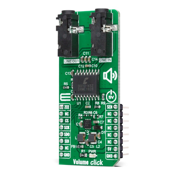
- 본 제품은 스테레오 디지털 볼륨 컨트롤 모듈 -CS3310입니다.
- CS3310 칩 기반으로 디자인된 제품으로, 2개의 독립적인 오디오 채널을 127dB의 조절가능 범위에서 조절이 가능합니다.
- 볼륨 조절은 0.5dB 스텝을 가지며 SPI 인터페이스를 지원합니다.
특징
-
Type Signal Processing Applications Can be used for remote audio volume control applications. On-board modules - CS3310, a complete stereo digital volume control designed specifically for audio systems from Cirrus Logic - LT3032, a dual 150mA positive and negative low noise low dropout linear regulator with micropower quiescent current from Analog Devices. Key Features Complete digital volume control, wide adjustable range, low distortion, low noise active output stage capable of driving a 600Ω load, and more. Interface SPI Compatibility mikroBUS Click board size L (57.15 x 25.4 mm) Input Voltage 5V -
Volume Click is based on the CS3310, a complete stereo digital volume control designed specifically for audio systems from Cirrus Logic. It features a 16-bit serial interface that controls two independent, low distortion audio channels. The left and right levels of the analog input channels are set by a 16-bit serial data word (the first 8 bits address the right while the remaining 8 bits address the left channel). The CS3310 includes an array of well-matched resistors and a low noise active output stage capable of driving a 600Ω load. A total adjustable range of 127dB, in 0.5dB steps, is achieved through 95.5dB of attenuation and 31.5dB of gain.
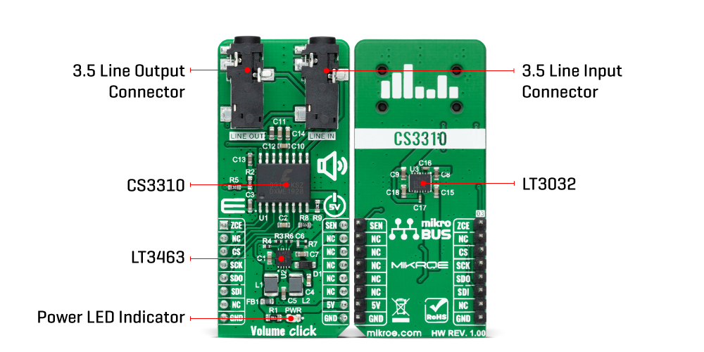
The digital section power supply of the Volume Click is achieved through a 5V pin from mikroBUS™ socket while the device itself is powered by ±5V from the LT3032, a dual 150mA positive and negative low noise low dropout linear regulator with micropower quiescent current from Analog Devices.
Volume Click communicates with MCU using the standard SPI serial interface with two additional GPIO pins that accept 16-bit data and enables the user to read the current volume setting. Those two GPIO pins brought with this Click board™ are used for Zero Crossing Enable and Hardware MUTE functions. Once in operation, the CS3310 can be brought to a muted state with the MUTE pin, labeled as SEN routed on the PWM pin of the mikroBUS™ socket, or by writing zeros to the volume control registers.
A volume control change occurs after the CS pin latches the data in the volume control data register, and two zero crossings are detected. The zero-crossing enable pin, labeled as ZCE routed on the AN pin of the mikroBUS™ socket, enables or disables the zero-crossing detection function as well as the 18ms time-out circuit. If two zero crossings are not detected within 18ms of the change in the CS pin, the new volume setting is implemented.
NOTE: Upon initial application of power, the SEN pin of the CS3310 should be set LOW to initiate a Power-Up sequence. This sequence sets the serial shift register and the volume control register to zero and performs an offset calibration. The device should remain muted until the supply voltages have settled to ensure accurate calibration.
This Click board™ is designed to be operated only with a 5V logic voltage level. A proper logic voltage level conversion should be performed before the Click board™ is used with MCUs with different logic levels.


